
 EN
 AR
 BG
 HR
 CS
 FR
 DE
 EL
 HI
 IT
 JA
 KO
 RO
 RU
 ES
 TL
 ID
 LT
 SK
 SL
 UK
 VI
 ET
 TH
 TR
 FA
 AF
 MS
 HY
 AZ
 KA
 BN
 LO
 LA
 MN
 NE
 MY
 KK
 UZ
 KY
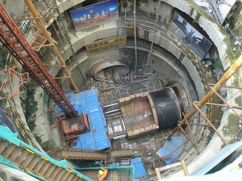
Designing an efficient pipe jacking system requires careful attention to multiple interconnected variables, with slurry line diameter and pump capacity standing as two of the most critical factors. The relationship between slurry line diameter and pump capacity directly influences the performance, reliability, and cost-effectiveness of the entire jacking operation. When slurry line diameter and pump capacity are mismatched, the system experiences pressure losses, reduced flushing efficiency, and accelerated wear on equipment. Understanding how slurry line diameter and pump capacity interact is essential for engineers and contractors who want to avoid costly delays and equipment failures during horizontal boring operations.
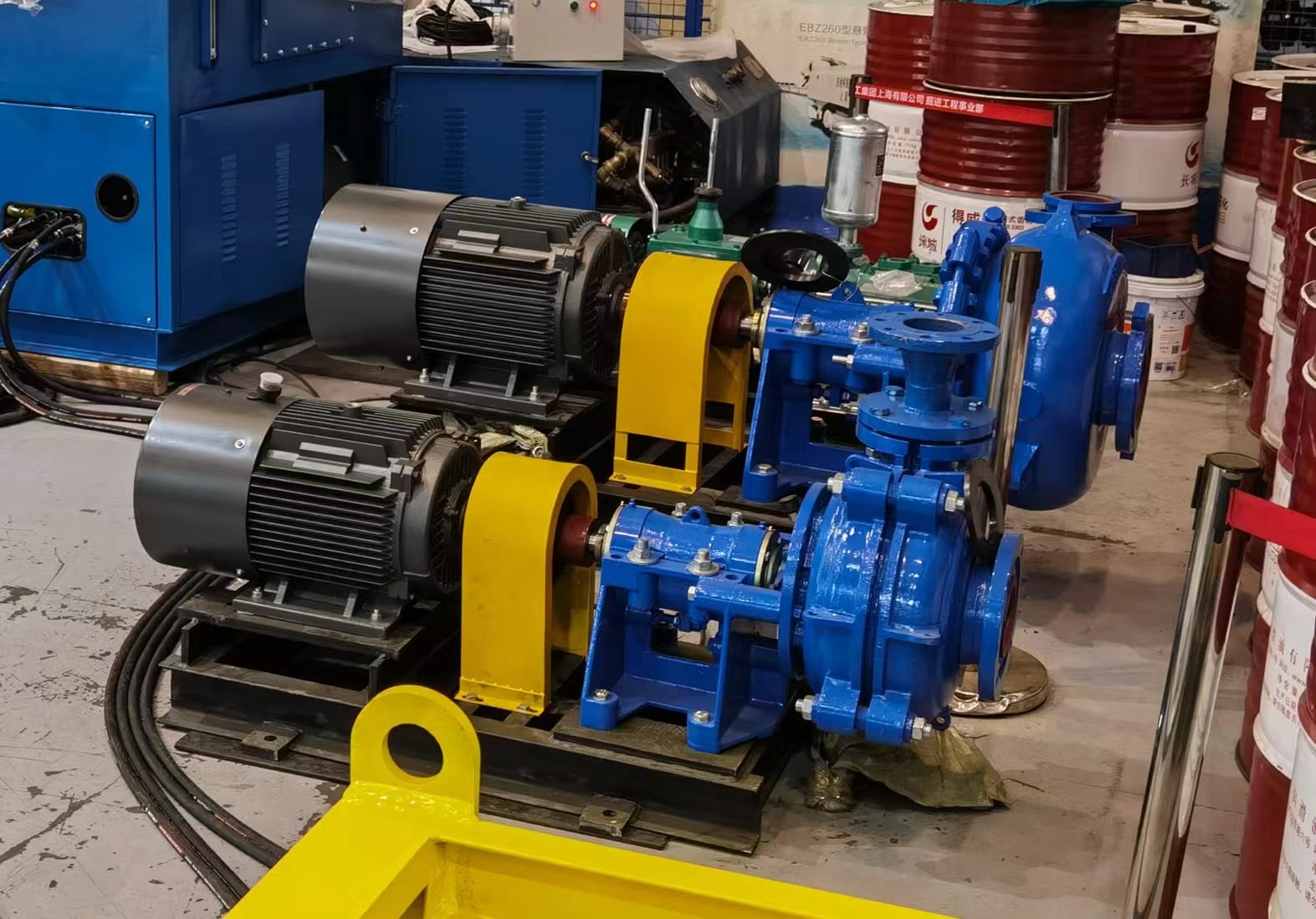
The slurry line diameter and pump capacity must work in harmony to transport excavated material, cool the cutting head, and maintain face stability throughout the bore. Selecting appropriate dimensions requires balancing flow velocity, pressure drop, and system economics. This article explores the fundamental principles that govern slurry line diameter and pump capacity decisions, examines how these factors integrate into overall pipe jacking system design, and provides practical guidance for sizing decisions in real-world projects.
Understanding Slurry Line Diameter and Pump Capacity Fundamentals
The Role of Slurry Line Diameter in System Efficiency
Slurry line diameter directly controls the velocity at which slurry travels through the pipe network. When slurry line diameter is too small, flow velocity increases, leading to higher friction losses and greater pressure demands on the pump. Conversely, when slurry line diameter is oversized, velocity decreases, reducing pressure losses but increasing capital costs and space requirements. The optimal slurry line diameter balances these competing demands, ensuring sufficient velocity to transport solids while minimizing energy consumption and pressure spikes that can damage equipment.
Industry standards recommend maintaining flow velocity between 1.0 and 1.5 meters per second in the slurry line diameter pipework for most soil conditions. This velocity range ensures effective sediment transport while preventing pipe abrasion and excessive pressure loss. When selecting slurry line diameter, engineers must also consider the specific gravity and particle size distribution of the excavated material, as heavier soils and larger particles require different slurry line diameter specifications than fine silts or clays. The relationship between these material properties and slurry line diameter sizing becomes increasingly important in challenging geology where uniform sizing assumptions may prove inadequate.
Pump Capacity and System Performance
Pump capacity determines the volume of slurry that circulates through the system per unit time, measured in cubic meters per hour or gallons per minute. The pump capacity must be sized to meet peak demand scenarios while maintaining stable operating conditions across varying boring phases. During initial boring phases when cutting head face pressures are minimal, pump capacity requirements are lower, but as depth increases and face pressures rise, the pump capacity must provide sufficient volume to maintain slurry circulation and face stability. Undersizing pump capacity creates bottlenecks that compromise system response and increase cutting head torque, while oversizing pump capacity wastes energy and increases equipment costs without corresponding performance benefits.
The pump capacity selection interacts directly with slurry line diameter sizing decisions because a given pump capacity delivers different velocities depending on the slurry line diameter of the pipes chosen. A pump capacity of 150 cubic meters per hour produces very different flow dynamics in a 150-millimeter versus a 200-millimeter slurry line diameter. This interdependency means that slurry line diameter and pump capacity decisions cannot be made independently; they must be evaluated together as an integrated system design parameter.
Integration of Slurry Line Diameter and Pump Capacity in Pipe Jacking System Design
Pressure Drop Calculations and Sizing Methodology
Calculating pressure drop across the slurry line diameter and distribution network is fundamental to pump capacity sizing. The Darcy-Weisbach equation and Hazen-Williams formulas provide the mathematical framework for estimating friction losses in pipes, accounting for slurry line diameter, roughness, and flow velocity. When slurry line diameter increases by one nominal size, friction losses typically decrease by approximately 30 to 40 percent, creating significant energy savings over the life of a project. Conversely, reducing slurry line diameter by one size can increase pressure requirements by 50 to 100 percent, depending on the specific flow rate and slurry properties.
System designers must calculate total pressure requirements by summing friction losses in the slurry line diameter pipework, elevation changes, restrictions at the cutting head, and safety margins. For a typical pipe jacking operation with 500 meters of boring distance, pressure drops in the slurry line diameter and return pipework can range from 5 to 15 bar, depending on whether a 150-millimeter or 250-millimeter slurry line diameter is selected. This pressure differential directly translates to pump selection and motor sizing decisions, making slurry line diameter and pump capacity calculations essential for cost-effective project execution.
Face Pressure Control and Slurry Line Diameter Coordination
Maintaining stable face pressure is critical for preventing ground collapse or excessive ground loss during pipe jacking operations. The slurry line diameter and pump capacity system must deliver sufficient slurry volume to maintain face pressure while minimizing pressure oscillations that can destabilize the bore. When slurry line diameter and pump capacity are properly matched, pressure regulation systems can respond effectively to changing ground conditions. If slurry line diameter and pump capacity are mismatched, such as when a small-diameter pipe is paired with a large-capacity pump, pressure spikes occur that may exceed safe operating limits or cause equipment damage.
Bentonite or polymer slurries used in slurry shield jacking operations have specific rheological properties that influence how slurry line diameter and pump capacity must be configured. Higher viscosity slurries require larger slurry line diameter to maintain target velocities and reduce pressure losses, or alternatively, larger pump capacity with smaller slurry line diameter if space constraints are limiting. The choice of slurry chemistry and corresponding slurry line diameter and pump capacity sizing represents a fundamental design decision that affects both operational performance and project economics.
Practical Application and Site Considerations for Slurry Line Diameter and Pump Capacity
Site Constraints and Slurry Line Diameter Selection
Real-world projects frequently encounter spatial limitations that constrain slurry line diameter and pump capacity choices. Urban sites with limited working pit dimensions may not accommodate the ideal slurry line diameter diameter pipes, requiring engineers to compensate with higher pump capacity or alternative circulation system configurations. In such situations, the cost and operational implications of using a smaller slurry line diameter with higher pump capacity must be carefully weighed against the structural, electrical, and operational expenses of fitting larger-diameter slurry line systems into confined spaces.
Ground conditions and boring length also influence slurry line diameter and pump capacity decisions. Long-distance drives through abrasive soils may justify investment in larger slurry line diameter to reduce friction losses and extend pump service life, while short drives through stable clay may function adequately with smaller slurry line diameter and higher pressure operation. Sand and gravel layers impose particular demands on slurry line diameter and pump capacity because particle sizes are larger and settling rates faster, requiring either larger slurry line diameter for improved velocity or higher pump capacity to maintain adequate circulation rates.
Monitoring and Adjustment Strategies
Experienced operators monitor pressure differentials, flow rates, and slurry return quality to identify when slurry line diameter and pump capacity selections are deviating from design assumptions. Real-time data from pressure sensors and flow meters provides the feedback needed to adjust pump speed or bypass rates to maintain optimal operating conditions. When slurry line diameter and pump capacity are properly sized, pressure remains relatively stable across boring phases; significant pressure variations may indicate that slurry line diameter and pump capacity are mismatched or that ground conditions have changed significantly from pre-bore investigations.
The slurry line diameter and pump capacity system should include instrumentation for measuring pressure, flow rate, and slurry density at key points along the circulation network. This data enables operators to diagnose problems quickly and implement corrective actions before equipment damage or operational delays occur. Modern slurry circulation systems incorporate variable-frequency drives on pump motors, allowing real-time adjustment of pump capacity to match changing operational demands, which is particularly valuable when actual slurry line diameter and pump capacity performance diverges from design calculations.
FAQ
What is the typical recommended flow velocity in slurry line diameter pipes for pipe jacking?
The industry standard for flow velocity in slurry line diameter pipes typically ranges from 1.0 to 1.5 meters per second. This velocity range ensures effective transport of excavated material while minimizing abrasion, pressure losses, and energy consumption. Higher velocities may be necessary in cohesionless soils where settling rates are faster, while lower velocities may be acceptable in clay-rich formations. The specific slurry line diameter selection must achieve the target velocity range based on the required pump capacity and system demand.
How do I calculate the correct slurry line diameter and pump capacity for my project?
Calculating slurry line diameter and pump capacity requires systematic steps: first, determine the required face pressure and volume circulation rate based on boring length, soil type, and cutting head design; second, select a preliminary slurry line diameter and calculate friction losses using Darcy-Weisbach or Hazen-Williams equations; third, size the pump capacity to overcome total system pressure while maintaining target velocity in the slurry line diameter; and finally, verify that selected slurry line diameter and pump capacity fit within site spatial and electrical constraints. Pre-bore investigations and similar project data provide essential input for accurate slurry line diameter and pump capacity estimates.
What happens when slurry line diameter and pump capacity are mismatched?
Mismatches between slurry line diameter and pump capacity create operational problems: if slurry line diameter is too small relative to pump capacity, excessive pressure develops, accelerating pipe wear and risking equipment damage; if slurry line diameter is oversized relative to pump capacity, flow velocity drops, reducing slurry transport effectiveness and allowing sediment settlement in pipes. Either scenario degrades system performance, increases maintenance costs, and may compromise boring progress or ground stability. Proper matching of slurry line diameter and pump capacity ensures stable, efficient operation throughout the jacking sequence.