
 EN
EN
 AR
AR BG
BG HR
HR CS
CS FR
FR DE
DE EL
EL HI
HI IT
IT JA
JA KO
KO RO
RO RU
RU ES
ES TL
TL ID
ID LT
LT SK
SK SL
SL UK
UK VI
VI ET
ET TH
TH TR
TR FA
FA AF
AF MS
MS HY
HY AZ
AZ KA
KA BN
BN LO
LO LA
LA MN
MN NE
NE MY
MY KK
KK UZ
UZ KY
KY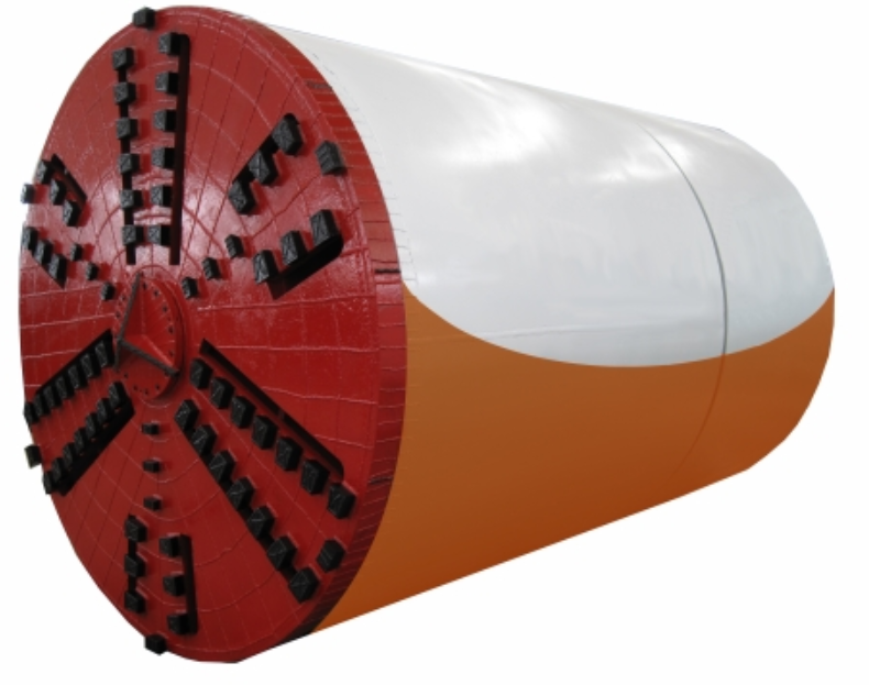
Underground pipe installation is one of the most technically demanding challenges in modern civil engineering. When traditional open-cut methods are used, the physical stress applied to pipe joints during backfilling, compaction, and soil settlement can cause misalignment, cracking, or outright failure. A microtunneling machine addresses these challenges at a fundamental level by controlling the forces that act on the pipeline throughout the entire installation process, drastically reducing the likelihood of joint damage from the moment the pipe enters the ground.
The engineering logic behind a microtunneling machine is built around precise, continuous advancement through soil while maintaining controlled jacking forces, stable bore alignment, and active face support. Each of these mechanisms contributes directly to protecting the structural integrity of pipe joints. Understanding why this technology is so effective at preventing joint damage requires a closer look at how ground forces interact with pipe strings during installation, and how the microtunneling machine systematically neutralizes each risk factor.
The Nature of Pipe Joint Damage During Underground Installation
Why Joints Are the Weakest Point in a Pipeline
In any segmental pipeline, the joint between two pipe sections represents a transition zone where material properties, tolerances, and load transfer mechanisms all converge. Unlike the pipe barrel itself, which is designed to resist uniform hoop stress, pipe joints are designed to transmit compressive jacking forces while accommodating small angular deflections. This dual requirement makes joints inherently more sensitive to overloading, eccentricity, and misalignment than any other part of the system.
When jacking forces become uneven—as they often do in open-face hand mining or auger boring—the resultant bending moment at the joint can exceed the design capacity of the gasket or the concrete face. Spalling, cracking, and rubber seal extrusion are common consequences. In pressurized pipelines, even minor joint damage can escalate into leakage, infiltration, or structural collapse over time. This is why controlling the force environment during installation is so critical, and it is exactly the problem that a microtunneling machine is engineered to solve.
How Soil Variability Amplifies Joint Risk
Soil conditions are rarely uniform along the length of a drive. Operators frequently encounter alternating layers of soft clay, dense gravel, cobbles, or water-saturated sand within a single bore. Each transition introduces a change in face resistance, which in turn affects the distribution of jacking load along the pipe string. Without a mechanized cutter head that continuously adapts to these changes, force spikes can develop at individual joints, creating localized stress concentrations that traditional installation methods cannot detect or correct in real time.
A microtunneling machine uses an earth pressure balance or slurry pressure balance system to maintain constant face support regardless of soil variability. By keeping the excavation face stable, the machine prevents sudden changes in resistance that would otherwise translate directly into shock loading at the nearest pipe joint. This proactive force management is one of the primary reasons why microtunneling delivers measurably better joint integrity compared to alternative trenchless methods.
How the Microtunneling Machine Controls Jacking Forces
Distributed Force Application Along the Pipe String
One of the most important mechanical features of a microtunneling machine system is the use of intermediate jacking stations. Rather than concentrating the entire jacking load at the launch shaft, intermediate stations divide the force requirement into manageable segments distributed along the pipe string. This means that no single joint is ever subjected to the full cumulative force needed to advance the entire pipeline. Each joint only carries the fraction of load needed to push the pipes in its immediate segment forward.
The result is a dramatic reduction in the compressive stress experienced at any individual joint. Engineers can calculate the maximum allowable jacking force for their chosen pipe specification and then configure the intermediate station spacing to ensure that force never approaches the joint's design limit. This calculated approach to force management is only possible when using a microtunneling machine because the technology allows real-time monitoring and adjustment of thrust from each station independently.
Steering Precision and Angular Deflection Control
Pipe joint damage often occurs not from pure axial compression but from angular loading caused by bore deviation. When a pipeline drifts off its design alignment, the correction process requires the machine to steer back onto grade, which introduces a bending component into the jacking force. If this angular deflection at any joint exceeds the manufacturer's tolerance, the concrete edge on one side of the joint will experience concentrated bearing stress while the opposite side loses contact entirely, creating an eccentrically loaded joint that is highly vulnerable to cracking.
A microtunneling machine uses a laser guidance system combined with hydraulic steering cylinders at the cutter head to maintain alignment within millimeter tolerances. Real-time survey data feeds back to the operator, who can make micro-corrections before cumulative deviation builds up. Because alignment is maintained continuously rather than corrected in large discrete steps, the angular deflection at any given joint remains well within safe limits throughout the entire drive. This steering precision is a defining characteristic of the microtunneling machine and one of its most powerful protections against joint damage.
Face Support Mechanisms and Ground Stability
Earth Pressure Balance as a Joint Protection Strategy
Ground instability at the excavation face is a primary driver of erratic jacking resistance. When the face is unsupported, soil can flow or collapse into the void ahead of the cutter head, creating voids around the pipe exterior, changing the lateral support conditions, and introducing uneven loads along the pipe string. A microtunneling machine equipped with earth pressure balance technology maintains continuous pressure on the excavation face by controlling the volume and rate of spoil removal relative to the advance rate.
This balance prevents the formation of ground voids that would otherwise allow the pipe to sag or deflect under gravity between support points. Sag introduces bending stress at every joint in the affected zone, and in long drives or soft ground conditions, this can become severe enough to cause joint failure even when axial jacking forces are within acceptable limits. By maintaining a stable, well-supported bore environment, the microtunneling machine eliminates this secondary mechanism of joint damage entirely.
Lubrication Systems and Skin Friction Reduction
As the pipe string advances through the bore, friction between the exterior pipe surface and the surrounding soil generates a continuous load that adds to the jacking force required at the launch shaft and intermediate stations. Without active friction reduction, this skin friction component can become dominant in long drives, pushing total jacking forces to levels that threaten joint integrity. A microtunneling machine addresses this through systematic injection of bentonite or polymer lubricant through ports in the pipe string, creating a continuous lubricating annulus around the pipe exterior.
The reduction in skin friction achieved through lubrication can be substantial, often cutting friction-related jacking force by fifty percent or more in favorable soil conditions. Lower total jacking force means lower stress at every joint in the string, directly reducing the risk of compressive overload. The microtunneling machine's ability to deliver lubrication systematically and reliably throughout the drive is a key engineering advantage that contributes significantly to long-term joint health.
Installation Accuracy and Its Effect on Long-Term Joint Integrity
Grade Control and Hydraulic Performance
A pipeline installed with a microtunneling machine achieves a level of grade accuracy that open-cut and many other trenchless methods simply cannot replicate. Maintaining consistent grade is important not just for hydraulic performance but also for long-term joint integrity. When a gravity sewer or drainage line is installed with slope variations caused by poor grade control, water can pond in low points, creating hydrostatic pressure differentials across joints that accelerate infiltration and chemical attack on rubber seals and concrete surfaces.
Over years of operation, these localized stress and chemical effects weaken joints progressively, ultimately leading to the same types of structural failures that poor installation quality causes immediately. The precision grade control delivered by a microtunneling machine prevents these long-term degradation pathways by ensuring that the pipeline geometry remains exactly as designed from day one. This is a dimension of joint protection that is often overlooked but becomes increasingly important as pipeline design lives extend to fifty years or more.
Avoiding Post-Installation Settlement and Secondary Stresses
Open-cut installation disrupts a large volume of soil around the pipeline, and no matter how carefully trench backfill is compacted, some degree of differential settlement will occur as the disturbed soil reconsolidates. This settlement imposes secondary bending stresses on the pipeline and its joints that were not present during installation. In contrast, a microtunneling machine installs the pipeline through undisturbed native soil, leaving the surrounding ground structure largely intact.
The undisturbed native soil provides immediate and uniform bedding support along the full length of the pipeline, eliminating the settlement-driven secondary stresses that cause progressive joint damage in open-cut installations. Over the operational life of the pipeline, this difference in initial ground disturbance translates into measurably better joint performance, fewer maintenance interventions, and a substantially lower risk of catastrophic failure. The microtunneling machine's approach to installation therefore protects joints not only during construction but for the entire service life of the asset.
Operational Monitoring and Real-Time Risk Management
Instrumentation and Force Monitoring Systems
Modern microtunneling machine systems are equipped with comprehensive instrumentation packages that monitor jacking force, face pressure, advance rate, torque, and alignment in real time. This data is displayed continuously to the operator and recorded for post-drive analysis. When any parameter approaches a threshold that could indicate risk to pipe joint integrity, the operator can immediately adjust operating conditions before damage occurs. This capability transforms joint protection from a passive design function into an active operational discipline.
The ability to detect and respond to anomalies in real time is a significant advantage over methods that rely entirely on pre-installation design calculations. Ground conditions change, unexpected obstructions occur, and equipment behavior can shift during long drives. The instrumentation integrated into a microtunneling machine gives operators the situational awareness needed to maintain joint safety even when conditions deviate from the design assumptions. This real-time risk management capability is one of the most compelling practical reasons why experienced project engineers specify a microtunneling machine for sensitive pipeline corridors.
Pre-Drive Planning and Pipe Specification Alignment
The risk reduction delivered by a microtunneling machine begins well before the first pipe enters the ground. The engineering workflow for microtunneling requires detailed pre-drive analysis of soil conditions, groundwater, drive length, and alignment geometry. This analysis directly informs the selection of pipe wall thickness, joint design, gasket specification, and intermediate station placement. The result is a fully integrated system where the pipe specification and the machine operating parameters are matched to each other and to the specific ground conditions of the project.
This integrated engineering approach means that every joint in the installed pipeline has been designed to handle the maximum forces it will realistically encounter, with appropriate safety margins. There is no guesswork, no reliance on field judgment about acceptable force levels, and no tolerance for approximation in alignment. The systematic rigor of the microtunneling machine workflow is itself a structural protection for pipe joints that extends from the design office through to the completion of the drive.
FAQ
What types of pipes are typically used with a microtunneling machine?
Reinforced concrete pipe, vitrified clay pipe, steel pipe, and glass fiber reinforced polymer pipe are all commonly used with a microtunneling machine. The selection depends on the application, ground chemistry, required hydraulic performance, and the specific jacking force demands of the drive. Each pipe type has defined joint systems engineered to work within the force and deflection parameters that microtunneling imposes.
How does a microtunneling machine differ from auger boring in terms of joint protection?
Auger boring advances a casing pipe using a rotating helical auger and provides limited control over face pressure, alignment accuracy, or jacking force distribution. This makes it significantly more prone to creating the force imbalances that damage pipe joints. A microtunneling machine provides continuous face support, laser-guided alignment, real-time force monitoring, and lubrication systems that collectively deliver a level of joint protection that auger boring fundamentally cannot match.
Can a microtunneling machine be used in very soft or waterlogged ground without increasing joint risk?
Yes. A microtunneling machine equipped with earth pressure balance or slurry circulation technology is specifically designed to handle soft, cohesive, or waterlogged ground conditions. These face support systems maintain bore stability and prevent the ground movement that would otherwise cause uneven pipe support and joint stress concentration. In fact, soft ground is one of the conditions where the joint protection advantages of a microtunneling machine are most clearly demonstrated compared to alternative installation methods.
How is jacking force monitored during a microtunneling machine drive?
Jacking force is monitored continuously through load cells installed at the main jacking frame and at each intermediate jacking station. These sensors transmit real-time data to the operator's control panel, where the readings are compared against pre-calculated maximum allowable values for each joint in the string. If force levels rise unexpectedly, the operator can slow the advance rate, increase lubrication injection, or activate additional intermediate stations to redistribute the load and protect joint integrity.
Table of Contents
- The Nature of Pipe Joint Damage During Underground Installation
- How the Microtunneling Machine Controls Jacking Forces
- Face Support Mechanisms and Ground Stability
- Installation Accuracy and Its Effect on Long-Term Joint Integrity
- Operational Monitoring and Real-Time Risk Management
-
FAQ
- What types of pipes are typically used with a microtunneling machine?
- How does a microtunneling machine differ from auger boring in terms of joint protection?
- Can a microtunneling machine be used in very soft or waterlogged ground without increasing joint risk?
- How is jacking force monitored during a microtunneling machine drive?