
 EN
 AR
 BG
 HR
 CS
 FR
 DE
 EL
 HI
 IT
 JA
 KO
 RO
 RU
 ES
 TL
 ID
 LT
 SK
 SL
 UK
 VI
 ET
 TH
 TR
 FA
 AF
 MS
 HY
 AZ
 KA
 BN
 LO
 LA
 MN
 NE
 MY
 KK
 UZ
 KY
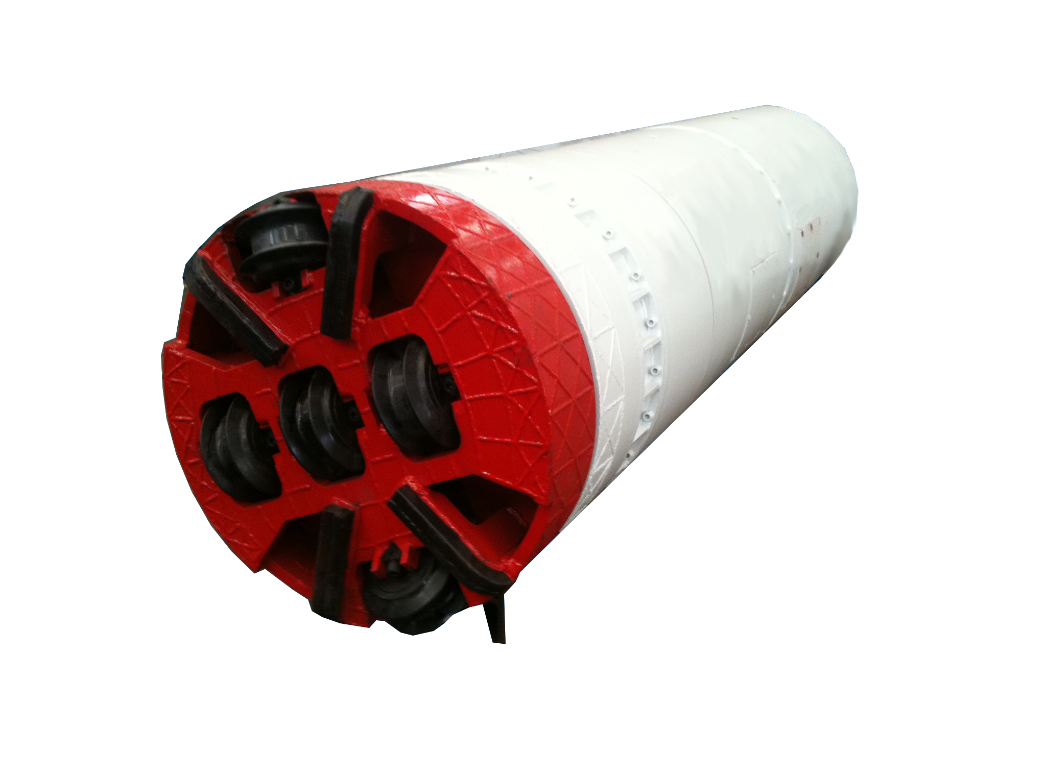
Hydraulic power pack sizing for pipe jacking equipment requires careful calculation of pressure, flow, and load specifications to ensure optimal performance and cost efficiency. The process of selecting the right hydraulic power pack sizing directly impacts the success or failure of your pipe jacking operation. Without proper hydraulic power pack sizing, equipment can fail under load, leading to project delays, equipment damage, and increased costs. Understanding the fundamentals of hydraulic power pack sizing helps contractors and engineers specify systems that deliver reliable performance across various geological conditions and project scales.
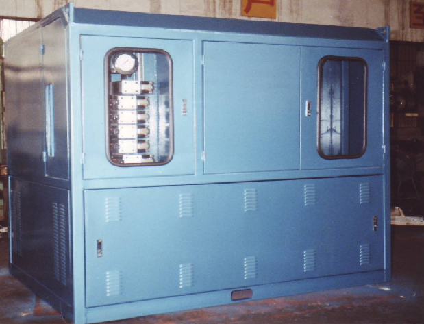
The complexity of hydraulic power pack sizing increases when considering the dynamic forces encountered during pipe jacking. Contractors must account for ground friction, pipe weight, steering cylinder demands, and contingency margins. Effective hydraulic power pack sizing ensures sufficient pump capacity and accumulator volume to handle peak demand cycles. This article explores the critical calculations and decision factors that professionals use when sizing hydraulic power packs for pipe jacking equipment in modern trenchless construction.
Understanding Pressure Requirements in Hydraulic Power Pack Sizing
Maximum Pressure and Safety Factor Considerations
Pressure is one of the three primary parameters in hydraulic power pack sizing. The jacking force required depends on pipe diameter, pipe weight, ground conditions, and friction resistance. Hydraulic power pack sizing must accommodate peak pressures that occur when pipes encounter dense soil layers or boulders. Most pipe jacking operations require pressure settings between 250 and 400 bar, though this varies significantly based on ground classification and project-specific conditions. A competent hydraulic power pack sizing calculation should include a safety factor of at least 1.3 to prevent system overload and component failure.
Pressure System Components and Reservoir Selection
The pressure rating affects every component in the hydraulic power pack sizing specification. Relief valves, hoses, cylinders, and manifold blocks must all match or exceed the calculated working pressure. Hydraulic power pack sizing also determines reservoir capacity, which influences cooling efficiency and fluid quality maintenance. Larger reservoirs accommodate thermal expansion, allow sediment settling, and provide volume for air separation. During hydraulic power pack sizing calculations, engineers typically specify reservoirs that hold two to three times the pump flow rate per minute, ensuring adequate residence time for fluid conditioning.
Flow Rate Calculation and Pump Capacity Determination
Jacking Velocity and Pump Displacement
Flow rate directly controls jacking velocity, and incorrect hydraulic power pack sizing in this dimension can severely impact project productivity. The required flow rate depends on desired jacking speed, cylinder bore diameter, and number of active jacking cylinders. Hydraulic power pack sizing formulas relate pump displacement to the required advance rate, typically ranging from 10 to 50 millimeters per second. A pump sized too small creates bottlenecks and extends project timelines, while over-sizing increases energy costs and heat generation unnecessarily. Proper hydraulic power pack sizing balances these competing factors by calculating exact pump displacement needed for planned jacking velocity.
Accumulator Sizing for Pressure Spikes and Load Variability
Beyond steady-state pump capacity, hydraulic power pack sizing must account for pressure peaks during difficult soil conditions. Accumulators absorb shock loads and pressure surges that would otherwise damage cylinders and manifolds. Hydraulic power pack sizing calculations determine accumulator volume by analyzing the pressure differential between normal operation and peak spike conditions. Typical accumulator sizing ranges from five to twenty percent of the total system volume. When hydraulic power pack sizing includes accumulators, the system becomes more responsive, smoother, and more durable over the project lifecycle.
Load Analysis and Jacking Force Estimation
Static Load Calculation from Pipe Weight and Ground Friction
Static loads form the baseline for all hydraulic power pack sizing calculations. The total jacking force must overcome the combined weight of pipes already in the shaft plus friction resistance from surrounding ground and pipe wall contact. Hydraulic power pack sizing engineers use empirical friction coefficients ranging from 0.2 to 0.8 depending on soil type, pipe material, and lubrication methods. The basic formula for required jacking force incorporates pipe weight, cross-sectional pipe area, and ground friction multiplier. Underestimating load during hydraulic power pack sizing is a common cause of system undersizing, while overestimating leads to unnecessary equipment cost.
Dynamic Loads, Steering Forces, and Contingency Margins
Real-world hydraulic power pack sizing must extend beyond static calculations to include steering cylinder demands and unexpected ground obstacles. Steering cylinders that control shield tilt and boom position require additional flow capacity during active course correction. Hydraulic power pack sizing practices in advanced projects apply load contingency factors between 1.2 and 1.5 to account for unforeseen conditions like boulders, hard clay bands, or water ingress. This contingency approach is more realistic than worst-case extreme scenarios. When hydraulic power pack sizing incorporates contingency thinking, the resulting systems handle project variability while maintaining acceptable performance margins.
Integration and System Specification
Matching Hydraulic Power Pack Sizing to Equipment Architecture
Once pressure, flow, and load calculations are complete, hydraulic power pack sizing must align with the specific jacking frame configuration. Some systems use single large cylinders, while others employ multiple smaller cylinders with load-sharing manifolds. Hydraulic power pack sizing specifications must account for cylinder synchronization requirements and pilot supply demands for directional control valves. The final hydraulic power pack sizing document becomes the engineering basis for equipment procurement, specifying pump type, motor size, tank volume, component ratings, and accumulator capacity. This comprehensive hydraulic power pack sizing specification ensures that manufacturers build systems meeting exact project requirements rather than applying generic defaults.
Thermal Management and Operating Efficiency
Hydraulic power pack sizing affects system heat generation because smaller pumps operating at higher pressure create more waste heat than properly sized systems. Inefficient hydraulic power pack sizing leads to higher operating temperatures, faster fluid degradation, and reduced component life. A hydraulic power pack sizing calculation that includes duty cycle analysis allows engineers to specify appropriate cooler capacity and heat rejection methods. Systems sized conservatively with adequate accumulator volume cycle more efficiently and require less active cooling. Professional hydraulic power pack sizing documentation typically includes expected operating temperatures and cooling system requirements.
FAQ
What is the most common pressure range used in hydraulic power pack sizing for pipe jacking?
Most pipe jacking operations use pressure settings between 250 and 400 bar in their hydraulic power pack sizing calculations. The exact pressure depends on pipe diameter, ground conditions, and project depth. Shallow soft ground projects may require only 200 bar, while deep difficult ground can demand 500 bar or higher. Professional hydraulic power pack sizing always specifies pressure with reference to the geological conditions and pipe specifications for that particular project.
How does accumulator sizing relate to overall hydraulic power pack sizing strategy?
Accumulators are essential to complete hydraulic power pack sizing because they absorb pressure spikes and provide emergency backup volume. Hydraulic power pack sizing calculations typically specify accumulators at five to twenty percent of total system volume depending on load variability. Including accumulators in your hydraulic power pack sizing makes the system more responsive, extends component life, and improves energy efficiency by allowing smaller primary pumps.
What contingency factor should be applied during hydraulic power pack sizing calculations?
Industry best practice for hydraulic power pack sizing applies contingency factors between 1.2 and 1.5 to account for unexpected ground conditions and measurement uncertainties. This approach is more realistic than worst-case extreme scenarios. Your specific hydraulic power pack sizing contingency factor should reflect the geological survey accuracy, site experience, and project risk tolerance. Conservative hydraulic power pack sizing with appropriate contingency prevents system failure and project delays while maintaining reasonable equipment costs.