
 EN
EN
 AR
AR BG
BG HR
HR CS
CS FR
FR DE
DE EL
EL HI
HI IT
IT JA
JA KO
KO RO
RO RU
RU ES
ES TL
TL ID
ID LT
LT SK
SK SL
SL UK
UK VI
VI ET
ET TH
TH TR
TR FA
FA AF
AF MS
MS HY
HY AZ
AZ KA
KA BN
BN LO
LO LA
LA MN
MN NE
NE MY
MY KK
KK UZ
UZ KY
KY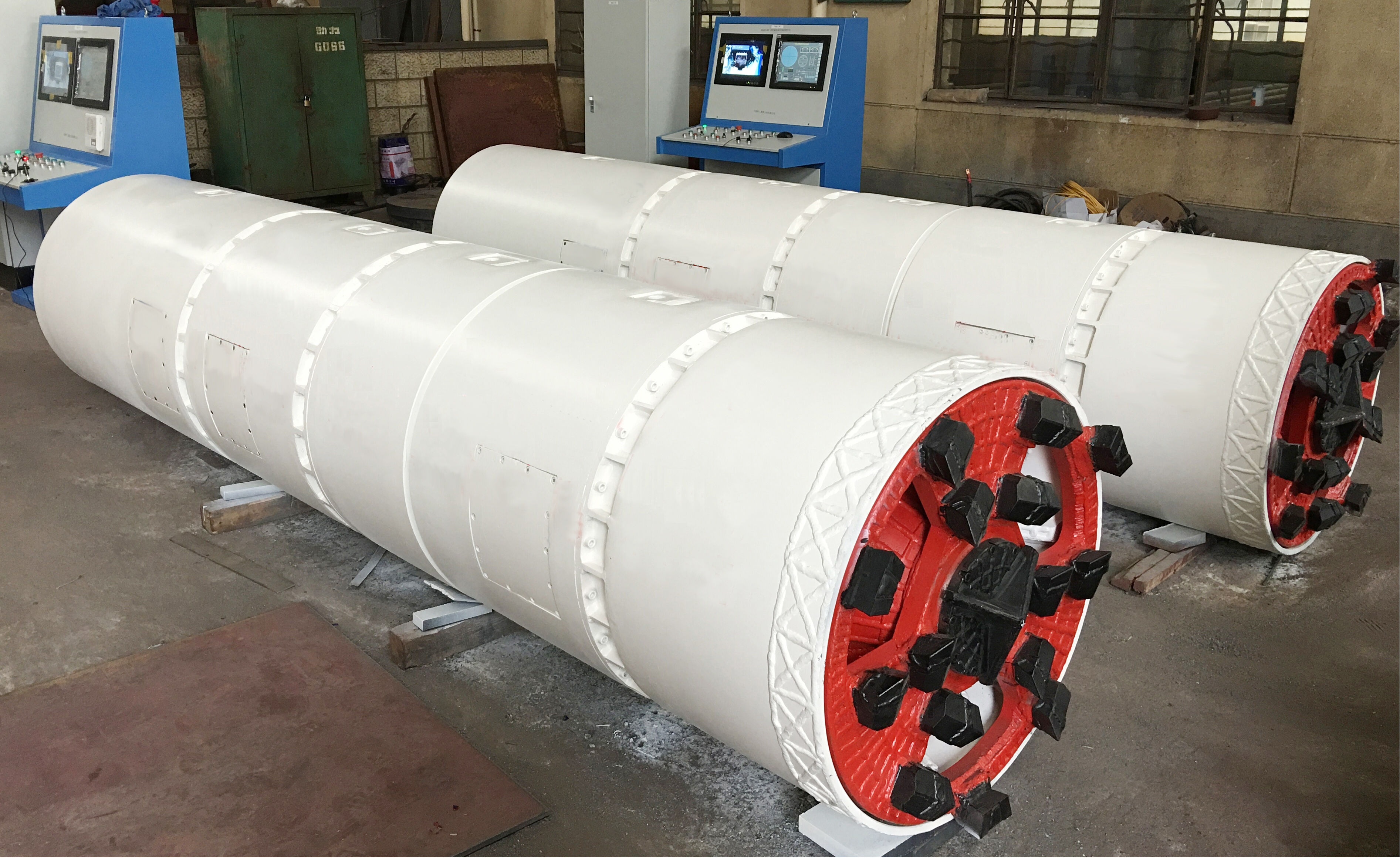
When underground utility contractors face tight urban corridors, river crossings, or infrastructure-dense zones, one critical question inevitably arises: can a microtunneling machine navigate a 50-meter radius curve? It is not an abstract engineering question. It directly determines whether a trenchless installation project is feasible, how much pre-planning is required, and which equipment specifications must be prioritized before mobilization.
The short answer is yes — under the right conditions, a microtunneling machine can successfully complete a 50-meter radius curve. However, this capability is not universal across all equipment types, pipe diameters, or soil profiles. Understanding the engineering logic, operational constraints, and decision criteria behind curved microtunneling drives is essential for project owners, design engineers, and construction teams who need reliable outcomes beneath sensitive urban environments.
Understanding Curved Drive Capability in Microtunneling
What Defines a Curve in Microtunneling Geometry
In trenchless engineering, a curve is defined by its radius — the tighter the radius, the more demanding the navigation challenge for any microtunneling machine. A 50-meter radius is considered a tight curve by industry standards. To put this in perspective, many standard microtunneling drives are designed for straight alignments or gentle curves exceeding 200 meters in radius. Dropping to 50 meters introduces meaningful geometric and mechanical complexity that must be engineered into both the equipment design and the drive plan.
The curve radius directly governs how much angular deviation the steering system must achieve at each pipe joint or machine articulation point. For a microtunneling machine operating at 50-meter radius, the angular offset per pipe segment becomes significant, especially as pipe diameter increases. Engineers must calculate allowable joint deflection angles based on pipe length, pipe material, and coupling type to confirm geometric feasibility before drilling begins.
Laser guidance and gyroscopic navigation systems are the two primary tools used to maintain accuracy during curved drives. A conventional laser guidance system is limited to straight-line reference, making it inadequate for tight curve navigation. Gyroscopic or automated total station systems are required to provide the real-time positional feedback that a microtunneling machine operator needs to execute and maintain a 50-meter radius alignment with precision.
Articulation Systems and Steering Mechanics
The ability of a microtunneling machine to follow a curved alignment depends fundamentally on its articulation system. Most modern microtunneling machines are equipped with steering cylinders that apply asymmetric thrust to redirect the cutterhead relative to the main body. In straight drives, these cylinders are used for minor course corrections. In curved drives, they must operate continuously and precisely to maintain the designed radius throughout the entire drive length.
Some microtunneling machines feature a double-articulation design, which provides an additional pivot point and expands the angular steering range. This configuration is particularly valuable for tight-radius applications, as it reduces the mechanical stress on the steering cylinders and distributes the geometric demand across two articulation joints rather than one. For a 50-meter radius drive, double-articulation machines often outperform single-articulation designs in both accuracy and mechanical reliability.
The hydraulic response speed and proportional control capability of the steering system also matter. In soft ground or variable soil conditions, the microtunneling machine may experience unexpected lateral forces that push it off alignment. A steering system with fast hydraulic response and fine proportional control allows operators to make small, continuous corrections without overcorrecting, which is critical for maintaining a smooth curved path rather than creating a series of angular deviations that approximate but do not match the intended arc.
Pipe Diameter, Pipe Material, and Their Effect on Curve Navigation
How Pipe Diameter Constrains Minimum Curve Radius
Pipe diameter is one of the most influential variables in determining whether a microtunneling machine can achieve a 50-meter radius curve. As pipe diameter increases, the length of individual pipe segments typically increases as well, and longer segments create larger angular offsets at each joint to follow the same curved path. This means that a 50-meter radius is more achievable with smaller-diameter pipes — typically in the 300mm to 600mm range — than with larger-diameter installations above 1000mm.
For larger-diameter microtunneling machine applications, contractors often need to shorten the individual pipe segment length to reduce the per-joint angular demand. Using shorter jacking pipes maintains the geometric integrity of the curve while preventing excessive stress concentration at the pipe joints. This modification must be specified during the procurement phase, as standard jacking pipe manufacturers offer limited-length segments for curved drive applications upon request.
The relationship between pipe diameter and curve radius is not simply linear. It involves the pipe's moment of inertia, the contact pressure between the pipe exterior and the surrounding ground, and the cumulative effect of jacking forces as the drive advances. A qualified geotechnical and structural engineer should verify that the selected pipe diameter is compatible with the 50-meter radius before a microtunneling machine is mobilized to the site.
Pipe Material Selection for Tight Curve Drives
Not all pipe materials perform equally when subjected to the bending and angular forces present during a curved microtunneling drive. Reinforced concrete jacking pipes, which are widely used in standard microtunneling machine applications, can handle curved drives when properly specified with appropriate joint designs, including cushion pads and machined end faces that distribute stress evenly across the joint interface. However, concrete pipes have limited angular deflection tolerance, which must be respected during the curve design.
Steel pipes, fiberglass pipes, and polymer concrete pipes offer different mechanical properties that may be advantageous for tight-radius applications. Steel pipes, for instance, can tolerate more deflection at joints and provide higher resistance to localized bending stress. However, they introduce other considerations such as corrosion protection, welding requirements, and handling logistics on the jobsite. The choice of pipe material should be made in conjunction with the selection of the microtunneling machine configuration, treating both as an integrated engineering system.
Pipe joint design is equally important. For a microtunneling machine operating on a 50-meter radius, joints must provide adequate angular flexibility while maintaining sufficient structural strength to transfer jacking loads. Specially designed spherical or tapered joint faces, combined with compressible cushion pads, are commonly specified to allow the required angular movement without creating stress concentrations that could crack the pipe or compromise the watertight seal.
Soil Conditions and Ground Behavior During Curved Drives
Influence of Soil Type on Steering Performance
The soil profile through which a microtunneling machine advances has a direct impact on its ability to navigate a tight curve. In cohesive soils such as clay, the ground offers relatively stable lateral support and predictable behavior, making it easier to maintain a consistent curved alignment. The microtunneling machine can apply steering corrections incrementally without triggering sudden lateral displacements, which is essential for achieving a smooth and accurate 50-meter radius drive.
In granular soils such as sand or gravel, the situation is more complex. These materials offer less lateral coherence, meaning that the ground around the microtunneling machine can shift or migrate in response to the steering forces applied. This creates a risk of uncontrolled over-steering or alignment deviation if the operator does not manage advance rates and steering inputs with precision. In water-bearing granular soils, face pressure management becomes even more critical to prevent ground loss, which would further destabilize the alignment.
Mixed-face conditions — where the microtunneling machine encounters alternating layers or pockets of different soil types — represent the most challenging scenario for curved drive execution. The differential resistance across the cutterhead can create unintended yaw or pitch forces that conflict with the intended steering direction. Projects in mixed-face conditions should include detailed pre-construction soil investigation, and the selected microtunneling machine should have adequate torque capacity and face pressure control to manage these transitions without losing alignment control.
Lubrication and Annular Void Management in Curves
During a curved microtunneling drive, the pipe string does not travel in a perfectly concentric path within the bored annulus. The geometry of the curve causes the pipe to bear against the soil on the outer arc, increasing friction on that side. Without proper lubrication management, this asymmetric friction can generate steering resistance that overwhelms the microtunneling machine's correction capability, pulling the drive off the intended curved alignment.
Bentonite slurry injection through lubrication ports distributed along the jacking string is the standard method used to reduce this friction. For curved drives, the lubrication plan must be adapted to account for the asymmetric friction distribution. Injection rates on the outer-arc side of the curve may need to be higher than those on the inner-arc side to achieve balanced lubrication and prevent the pipe string from migrating against the soil boundary.
Proper lubrication not only reduces jacking force requirements but also protects the pipe joints from excessive lateral loading caused by asymmetric ground contact. A microtunneling machine project manager should include curved-drive lubrication protocols in the method statement, specifying injection volume targets, pressure limits, and monitoring intervals that reflect the unique demands of a 50-meter radius alignment rather than defaulting to a standard straight-drive lubrication plan.
Planning and Execution Considerations for 50-Meter Radius Drives
Pre-Construction Engineering Requirements
Executing a curved drive with a microtunneling machine at 50-meter radius requires a higher level of pre-construction engineering than a standard straight drive. The project team must produce detailed alignment drawings that specify the curve geometry in three-dimensional coordinates, allowing the guidance system to be programmed with accurate target positions at regular intervals along the drive path. These drawings must also confirm that the selected pipe system can geometrically follow the curve without exceeding joint deflection limits.
Jacking force calculations for curved drives must incorporate the additional friction and steering resistance generated by the curved alignment. Intermediate jacking stations — sometimes called interjacks — may be required to distribute the total jacking load across the pipe string and prevent the cumulative force from exceeding the allowable pipe load capacity. The number and placement of interjacks must be designed based on the specific curve geometry, soil friction coefficients, and pipe material properties relevant to the project.
The launch shaft and reception shaft must be positioned and constructed to accommodate the microtunneling machine's entry and exit angles as defined by the curved alignment. If the curve begins immediately after launch, the shaft geometry must allow the machine to initiate the steering correction without being constrained by the shaft wall or the entry seal. These construction details are often overlooked in early project planning but can cause significant schedule disruptions if not resolved before machine mobilization.
Operational Monitoring and Real-Time Correction
During the execution of a curved drive, real-time monitoring is not optional — it is a fundamental operational requirement. The microtunneling machine operator must have continuous access to positional data from the guidance system, jacking force readings from the thrust frame and interjack stations, and face pressure feedback from the cutterhead instruments. Together, these data streams allow the operator to detect alignment deviations early and apply corrective steering inputs before the deviation accumulates beyond acceptable tolerance.
Advance rate management is a critical operational variable in curved drives. Advancing too quickly reduces the time available for steering corrections and increases the risk of exceeding joint deflection limits at individual pipe connections. Advancing too slowly can cause the annular lubrication to drain or consolidate, increasing friction and making steering more difficult. Experienced microtunneling machine operators understand this balance and adjust advance rates dynamically based on real-time feedback rather than following a fixed rate set during pre-construction planning.
Post-drive as-built surveys are equally important for confirming that the installed pipe system follows the designed 50-meter radius alignment within specified tolerances. Deviations identified during the as-built survey may require remedial action such as grouting or joint adjustment, and they provide valuable lessons for future curved drives. Documenting the full operational record of the microtunneling machine drive — including steering inputs, jacking forces, and guidance readings — creates a project knowledge base that improves planning accuracy for subsequent similar projects.
FAQ
What is the tightest curve radius a microtunneling machine can typically achieve?
The minimum achievable curve radius for a microtunneling machine depends on the machine model, pipe diameter, articulation design, and soil conditions. Many modern machines with double-articulation steering systems can achieve radii as tight as 30 to 50 meters in favorable ground conditions with smaller pipe diameters. Standard machines without specialized articulation are generally limited to radii of 100 meters or more. Always consult the equipment manufacturer's specifications and conduct a project-specific feasibility assessment before committing to a tight-radius drive plan.
Does a 50-meter radius curve significantly increase the jacking force required?
Yes, curved drives inherently generate higher jacking forces than straight drives of equivalent length. The asymmetric friction distribution along the outer arc of the curve, combined with the steering resistance from the soil, increases the total thrust demand on the microtunneling machine's jacking system. Depending on soil type, pipe diameter, and lubrication effectiveness, jacking forces on curved drives can be 20 to 50 percent higher than comparable straight drives. This must be accounted for in jacking force calculations and pipe structural capacity assessments during the design phase.
Can the guidance system accurately track a microtunneling machine through a 50-meter radius curve?
Standard laser-based guidance systems are designed for straight drives and cannot accurately track a microtunneling machine through a tight curve. For curved drives at 50-meter radius, gyroscopic guidance systems or automated total station systems are required. These technologies provide continuous three-dimensional positional updates that allow the operator to monitor alignment relative to the designed curve in real time. Selecting the appropriate guidance technology is one of the most important pre-construction decisions for any curved microtunneling drive project.
Is a 50-meter radius microtunneling drive suitable for all pipe diameters?
A 50-meter radius is more readily achievable with smaller pipe diameters, typically below 800mm, where shorter pipe segments and more flexible joint systems can accommodate the required angular deflection per joint. For larger diameters above 1000mm, achieving a 50-meter radius becomes significantly more challenging and may require specially designed short-length pipe segments, modified joint systems, and a microtunneling machine with enhanced steering capacity. Each application must be evaluated individually based on pipe geometry, joint specifications, and the selected machine's steering capability.
Table of Contents
- Understanding Curved Drive Capability in Microtunneling
- Pipe Diameter, Pipe Material, and Their Effect on Curve Navigation
- Soil Conditions and Ground Behavior During Curved Drives
- Planning and Execution Considerations for 50-Meter Radius Drives
-
FAQ
- What is the tightest curve radius a microtunneling machine can typically achieve?
- Does a 50-meter radius curve significantly increase the jacking force required?
- Can the guidance system accurately track a microtunneling machine through a 50-meter radius curve?
- Is a 50-meter radius microtunneling drive suitable for all pipe diameters?