
 EN
EN
 AR
AR BG
BG HR
HR CS
CS FR
FR DE
DE EL
EL HI
HI IT
IT JA
JA KO
KO RO
RO RU
RU ES
ES TL
TL ID
ID LT
LT SK
SK SL
SL UK
UK VI
VI ET
ET TH
TH TR
TR FA
FA AF
AF MS
MS HY
HY AZ
AZ KA
KA BN
BN LO
LO LA
LA MN
MN NE
NE MY
MY KK
KK UZ
UZ KY
KY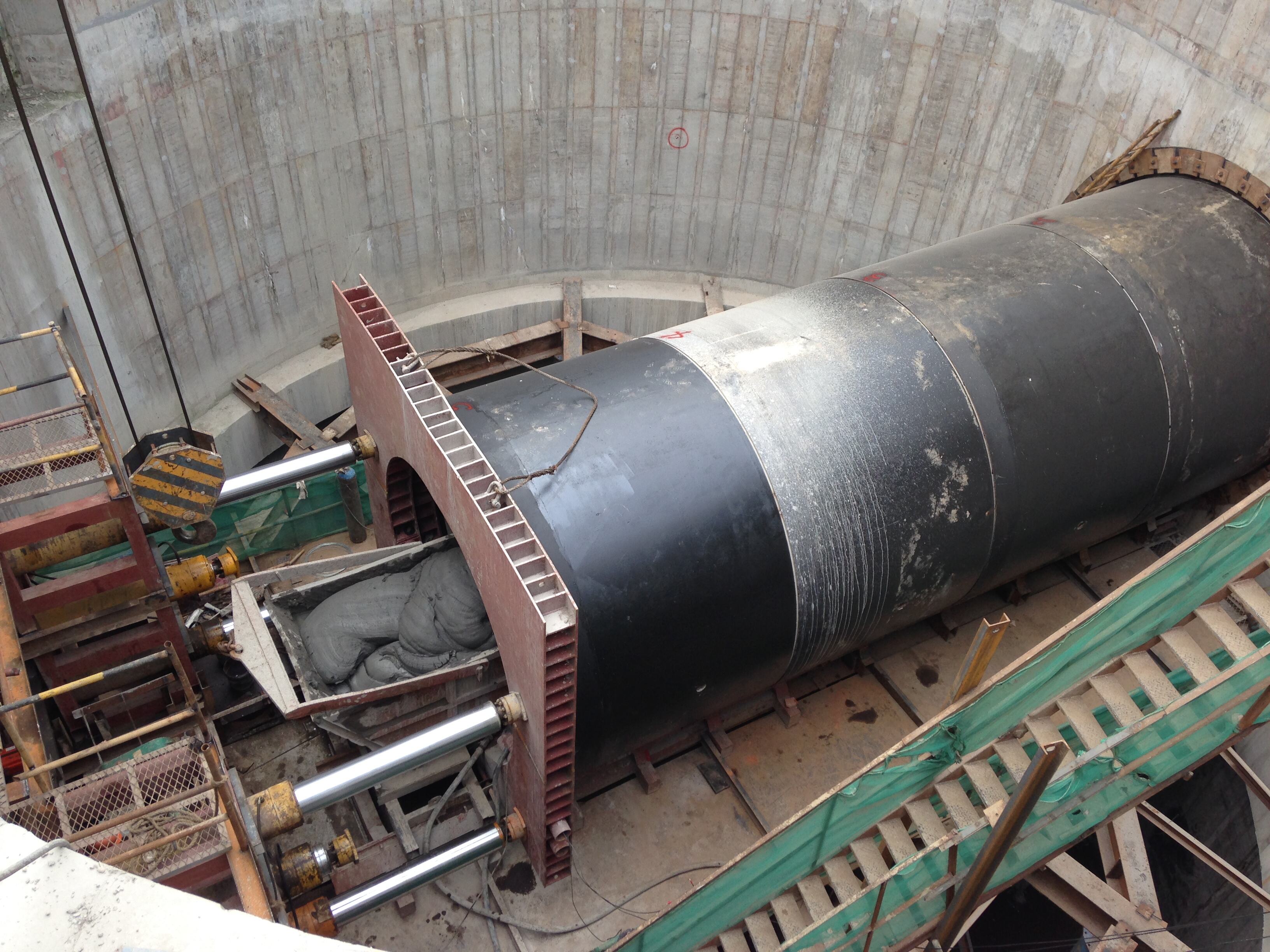
Միկրոթունելավորման մեքենայի համար ճիշտ մխոցման ուժի ընտրությունը մի միկրոհորատման մեքենա աշխատել խիտ ավազում ցանկացած առանց փոսի շինարարական նախագծում մեկն է ամենակարևոր ճարտարագիտական որոշումներից: Եթե այն թեթևացնեք, կվտանգվեն շարժման դադարեցումը, խողովակների վնասվելը կամ կատաստրոֆալ նախագծի հետաձգումները: Եթե այն գերագնահատեք, կհանդիպեք ավելցուկային սարքավորումների ծախսերի, մեխանիզմի մեջ մտնող բաղադրիչների չափից շատ մաշվելու և թունելի դիրքից վերև գտնվող հողի անցակայունության հնարավորությանը: Այս թիվը ճիշտ որոշելու համար անհրաժեշտ է համակարգված հասկացություն հողի մեխանիկայի, մեքենայի հնարավորությունների և շահագործման փոփոխականների մասին՝ դրանք միասին աշխատելու պայմաններում:
Խիտ ավազը ցանկացած միկրոթունելավորման մեքենայի համար ստեղծում է յուրահատուկ դժվարին միջավայր: Նրա բարձր ներքին շփման անկյունը, խողովակաշարի շուրջ կամարավորվելու և արգելափակվելու հակվածությունը, ինչպես նաև ստորերկրյա ջրերի պայմանների նկատմամբ զգայունությունը ստեղծում են դինամիկ բեռնվածության պրոֆիլ, որը շարունակաբար փոխվում է անցման ընթացքում: Ի տարբերություն մեղմ կավի կամ թեթև լցվածքի՝ խիտ ավազը դիմադրում է կտրմանը և տեղաշարժին, միաժամանակ առաջացնելով բարձրացված ճակատային ճնշում, մակերևույթային շփման դիմադրություն և կրող դիմադրություն: Այս ուժերի հասկանալը և դրանց ճշգրիտ հաշվարկը մեքենայի տեղափոխման սկսելուց առաջ հանդիսանում է հաջող իրականացված խողովակային մխոցավորման արշավի հիմքը:
Խիտ ավազում միկրոթունելավորման մեքենայի վրա ազդող ուժերի հասկանալը
Ճակատային դիմադրություն և կտրման պտտման մոմենտի պահանջներ
Երբ միկրոթունելավորման մեքենան առաջանում է խիտ ավազով, սղոցագլուխը ստիպված է հաղթահարել ճակատային պասիվ հողային ճնշումը: Խիտ ավազը ունի համեմատաբար բարձր շփման անկյուն՝ սովորաբար 35–45 աստիճանի սահմաններում՝ կախված հատիկների չափից, գրադացիայից և հարաբերական խտությունից: Սա ուղղակիորեն արտահայտվում է բարձրացված ճակատային դիմադրությամբ, որը պետք է հաշվի առնվի որպես ընդհանուր մխոցային ուժի հիմնարար բաղադրիչ: Սղոցագլխի երկրաչափական ձևը, բացվածքների հարաբերական մակերեսը և կտրող գործիքների դասավորությունը բոլորը ազդում են մեքենայի նյութի մասնատման և հեռացման արդյունավետության վրա, սակայն հիմնարար հողային ճնշումը մնում է կառավարող փոփոխական:
Միկրոթունելավորման մեքենան պետք է պահպանի հավասարակշռված ճակատային ճնշում՝ խուսափելու համար մակերևույթի խորտակման կամ չափազանց բարձր ճնշման պատճառով բարձրացման հետևանքներից: Խիտ ավազում այս հավասարակշռությունը հասնելու համար անհրաժեշտ է իրական ժամանակում հսկել սուզիկի կամ գետնի ճնշումը՝ կախված մեքենայի տեսակից: Օպերատորները, ովքեր հիմնականում հենվում են ստատիկ նախնական հաշվարկների վրա, հաճախ հանդիպում են անսպասելի կտրուկ աճի կտրման դիմադրության մեջ, երբ խտությունը մեծանում է խորության հետ մեկտեղ կամ երբ ստորգետնյա ջրերի պայմանները փոխվում են: Ճնշման անընդհատ հետադարձ կապի ներդրումը մխոցման ուժի կառավարման մեջ ոչ թե ընտրովի է, այլ՝ շահագործման համար անհրաժեշտ:
Կտրման պտտման մոմենտը և հրման ուժը փոխկապակցված են։ Խիտ ավազի դեմ պայքարող կտրիչ գլուխը պահանջում է մեծ պտտման մոմենտ, և եթե մեքենան միաժամանակ թույլ հրման ուժի տակ է, ապա այն կարող է կանգնել կամ առաջացնել սարքավորման ամբողջ ամրակայման համակարգի վրա չափազանց մեծ մաշվածություն։ Հրման շրջանակը պետք է կարողանա ապահովել հարթ և հաստատուն ուժի աճ, որը թույլ է տալիս օպերատորին արձագանքել առաջին ճակատի վիճակում տեղի ունեցող փոփոխություններին՝ առանց սուր բեռնվածության վերաբարձրացումների, որոնք կարող են լարել խողովակային շարքը կամ շեղել մեքենան ճիշտ դիրքից։
Խողովակային շարքի երկայնքով մակերևույթային շփման ուժ
Շատ խիտ ավազով երկար մետաղալարի մեջ մտցնելու ընթացքում ընդհանուր բարձրացման ուժի գերակշռող ներդրումը կտրման մակերեսից դուրս գտնվող մակերևույթային շփման ուժն է, որը ազդում է տեղադրված խողովակի ամբողջ երկարությամբ: Այս շփումը առաջանում է խողովակի արտաքին մակերևույթի և շրջապատող հողի միջև և մեծանում է մետաղալարի մեջ մտցնելու երկարության հետ համեմատաբար: Խիտ ավազում խողովակի և հողի միջև շփման գործակիցը մեծ է, քան կապված հողերում, իսկ խողովակի մակերևույթին ուղղահայաց ազդող կողային երկրաշարժային ճնշումը զգալիորեն մեծացնում է շփման բեռը:
Բենտոնիտային սուզվածքով շարժաբանումը խիտ ավազով միկրոթունելավորման ժամանակ մաշվածության կառավարման հիմնական միջոցառումն է: Լավ նախագծված շարժաբանման համակարգը բենտոնիտը ներարկում է խողովակաշարի երկայնքով տեղադրված ներարկման պորտերի միջոցով՝ ստեղծելով ցածր մաշվածության օղակաձև գոտի խողովակի արտաքին մակերեսի շուրջ: Սակայն խիտ ավազը կարող է արագ տեղափոխել բենտոնիտը օղակաձև գոտուց դուրս, հատկապես բարձր թափանցելիությամբ ապարային ձևավորումներում: Ամբողջ աշխատանքի ընթացքում շարժաբանման ճնշման և ներարկման ծավալի անհրաժեշտ մակարդակը պահպանելը կարևոր է մաշվածության մեծությունը հաշվարկված սահմաններում պահելու համար:
Ինժեներները, հաշվարկելով բարձրացման ուժը, ստիպված են հաշվի առնել իրական, այլ ոչ թե իդեալական շփման գործակիցը: Ավազում քսված պայմանների համար հրապարակված արժեքները սովորաբար տատանվում են 0,1–0,3 սահմաններում, սակայն դաշտային պայմանները՝ ներառյալ քսման մասնակի կորուստը, խողովակի շուրջ հողի սեղմվելը և հողի խողովակի դեմ կոնսոլիդացվելը թույլ տվող մեքենայական մուտքի ընդհատումները, կարող են էապես բարձրացնել արդյունավետ շփման գործակիցը: Պահպանողական շփման գործակցի օգտագործումը և այդ գործակցի հասնելու համար քսման ակտիվ կառավարումը շատ ավելի հուսալի են, քան այն օպտիմիստական տեսական արժեքներին հիմնվելը:
Խիտ ավազի պայմաններում ընդհանուր բարձրացման ուժի հաշվարկը
Հիմնական բարձրացման ուժի բանաձևը և դրա բաղադրիչները
Մայրուղու մեջ փոքր տրամագծի խորհրդատվական մեքենայի անհրաժեշտ ընդհանուր բարձրացման ուժը հավասար է ճաատային դիմադրության ուժի և ամբողջ խողովակաշարի երկայնքով մակերևույթային շփման ուժի գումարին: Ճակատային դիմադրությունը հաշվարկվում է որպես հորատման ճակատի մակերեսի և թունելի ճակատում գործող հողի ու ջրի զտված ճնշման արտադրյալ՝ ճշգրտված դիմադրության գործակցով, որը հաշվի է առնում կտրող գործիքների արդյունավետությունը և հողի խախտումը: Մակերևույթային շփումը հաշվարկվում է խողովակի պարագիծը բազմապատկելով շարժման երկարությամբ, խողովակի վրա ազդող նորմալ լարվածությամբ և խողովակ-հող սահմանի շփման գործակցով:
Խիտ ավազում՝ բարձր ջրատար շերտի պայմաններում, պետք է օգտագործվի արդյունավետ լարվածության մոտեցումը՝ ընդհանուր լարվածության փոխարեն: Ստորերկրյա ջրի ճնշումը ուղղակիորեն ավելանում է ճակատային մակերևույթի բեռնվածության հավասարակշռին և մեծացնում է խողովակաշարի վրա ազդող նորմալ լարվածությունը, ինչը միաժամանակ մեծացնում է ճակատային դիմադրությունն ու մակերևույթային շփման ուժը: Ջրատար շերտից ստորև աշխատող միկրոթունելավորման մեքենան խիտ, ջրով հագեցած ավազում կդիմանա զգալիորեն ավելի բարձր մխման ուժի պահանջների, քան նույն մեքենան՝ նույն խորության վրա չոր պայմաններում աշխատելիս, նույնիսկ նույն հողի խտության դեպքում:
Անվտանգության գործակիցները կիրառվում են հաշվարկված բարձրացման ուժի վրա՝ բարձրացման համակարգի անհրաժեշտ հզորությունը որոշելու համար: Բարդ հողային պայմաններում սովորաբար կիրառվում է 1,5–2,0 գործակիցը: Այս արժեքը երաշխավորում է, որ հողի դիմադրության անսպասելի մեծացումը՝ բազուկների, ցեմենտավորված շերտերի կամ քսանյութի անհաջողության պատճառով, չի գերազանցի խողովակի կամ հրման շրջանակի մեխանիկական սահմանափակումները: Միկրոթունելավորման մեքենայի նշված բարձրացման հզորությունը պետք է համեմատաբար գերազանցի այս գործակցով բազմապատկված ընդհանուր բարձրացման ուժի արժեքը՝ նախքան նախագծի իրականացման հաստատումը:
Միջանկյալ բարձրացման կայանները և դրանց դերը ուժի բաշխման մեջ
Երկար հեռավորության շարժման դեպքում խիտ ավազում բարձրացման ուժի կուտակումը կարող է գերազանցել կամ խողովակի կառուցվածքային կայունությունը, կամ հիմնական բարձրացման շրջանակի առավելագույն մխոցային ուժը: Միջանկյալ բարձրացման կայանները, որոնք հայտնի են նաև որպես միջանկյալ բարձրացման սարքեր (interjacks), հիդրավլիկ մխոցների համալիրներ են, որոնք տեղադրվում են խողովակի շարքում՝ նախապես պլանավորված միջակայքերով: Դրանք խողովակի շարքը բաժանում են ավելի կարճ հատվածների և թույլ են տալիս յուրաքանչյուր հատվածը առանձին մխել առաջ, ինչը կանխում է ընդհանուր բեռի միաժամանակյա կուտակումը խողովակի ամբողջ երկարությամբ:
Միջանկյալ բարձրացման կայանների տեղադրումը պետք է հաշվարկվի համախմբված շփման բեռնվածքի գնահատականների հիման վրա՝ յուրաքանչյուր շահագործման փուլում: Խիտ ավազում, որտեղ անհրաժեշտ է բարձր քանակությամբ քսանյութ, կայանները սովորաբար տեղադրվում են ավելի մոտ մեկը մյուսին, քան կապված հողերում: Յուրաքանչյուր կայան պետք է համատեղելի լինի մայրուղային խորհրդատվական մեքենայի կառավարման համակարգի հետ՝ հնարավորություն տալով համակարգված աշխատանք իրականացնել, որը պահպանում է խողովակաշարի անընդհատ շարժումը և կանխում է հողի կուտակումը կանգնած խողովակի հատվածների դեմ կանգառների ժամանակ:
Միջանկյալ բարձրացման կայանների օգտագործումը համեմատաբար երկար հնարավոր շարժման երկարություն է ապահովում տրված խողովակի սպեցիֆիկացիայի և բարձրացման շրջանակի հզորության դեպքում: Սակայն յուրաքանչյուր կայան մեխանիկական բարդություն է ավելացնում, ստեղծում է հնարավոր չճշտությունների կետեր և պահանջում է շատ համարձակ պլանավորում քսանյութի շրջանառության համար: Խիտ ավազով հողերում իրականացվող 150–200 մետրից ավելի երկար նախագծերը գրեթե միշտ պահանջում են առնվազն մեկ միջանկյալ կայան, իսկ նախագծման փուլում բարձրացման ուժի համար կատարվող համարակալված մոդելավորումը ճշգրտորեն որոշում է, թե որտեղ և քանի կայան է անհրաժեշտ:
Բարձրացման ուժի սահմանման առաջ հողի հետազոտության պահանջներ
Բարձրացման ուժի գնահատման համար կարևոր գեոտեխնիկական տվյալներ
Մանրաթելային թունելավորման մեքենայի ճշգրիտ բարձրացման ուժի սահմանումը սկսվում է բարձրորակ գեոտեխնիկական հետազոտությունից: Խիտ ավազային միջավայրում ամենացուցադրական փորձարկումների տվյալները ստացվում են ստանդարտ թրթռացման փորձարկումներից (SPT), կոնային թրթռացման փորձարկումներից (CPT) և լաբորատորիայում կատարվող եռառանցքային շրջանային ճկման փորձարկումներից, որոնք ուղղակիորեն չափում են շփման անկյունը, հարաբերական խիտությունը և սեղմվելիությունը: Թունելի հորիզոնտում SPT N-արժեքները, որոնք գերազանցում են 30-ը, հանդիսանում են խիտ ավազային պայմանների ուժեղ ցուցանիշ և պահանջում են ստանդարտ բարձրացման ուժի գնահատականների վերանայում դեպի վեր:
Մասնիկների չափսերի բաշխումը նույնպես հավասարապես կարևոր է: Լավ գրադացված խիտ ավազները, որոնք պարունակում են տարբեր չափսերի մասնիկներ, ավելի ագրեսիվ են միմյանց մեջ մտնում խողովակի շուրջ և ավելի ուժեղ են դիմադրում բենտոնիտային քսուքի ներթափանցմանը, քան համասեռ գրադացված ավազները: D50 հատիկային չափսի և համասեռության գործակցի մասին տեղեկատվությունը օգնում է ինժեներներին ընտրել համապատասխան բենտոնիտային քսուքի ծանրությունը և ներմուծման ճնշումը, ինչպես նաև ճշգրտել բարձրացման ուժի հաշվարկներում օգտագործվող շփման գործակցի ենթադրությունը:
Ստորգետնյա ջրերի վիճակը պետք է լիովին բնութագրվի, ներառյալ սեզոնային տատանումները: Չորային սեզոնի հողային պայմաններում նախագծված միկրոթունելային մեքենայի շարժիչը կարող է զգալիորեն ավելի բարձր հիդրոստատիկ ճնշման հանդիպել, եթե շինարարության ընթացքում ստորգետնյա ջրերի մակարդակը բարձրանա: Մոնիթորինգի ժամանակահատվածում պիեզոմետրի ցուցմունքները տալիս են ստորգետնյա ջրերի դինամիկայի ամենահուսալի պատկերը, և բարձրացման ուժի հաշվարկները պետք է հիմնված լինեն ստորգետնյա ջրերի ամենավատ հավաստի վիճակի վրա, այլ ոչ թե դիտարկվող միջին մակարդակի վրա:
Փորձարարական շարժումների և մոնիտորինգի տվյալների օգտագործումը ուժի ենթադրությունների վավերացման համար
Նույնիսկ հիմնավոր գեոտեխնիկական հետազոտության դեպքում մանրածալաքարային խողովակավորման մեքենայի շարժման վաղ փուլերում իրական ժամանակում վերահսկողությունը ապահովում է նախնական շարժման ջեքինգային ուժի հաշվարկների ամենաճշգրտ վավերացումը: Շատ ժամանակակից մանրածալաքարային խողովակավորման համակարգեր անընդհատ գրանցում են ջեքինգային ուժը, առաջխաղացման արագությունը, կտրող գլխի պտտման մոմենտը և ճակատային ճնշումը, ստեղծելով իրական ժամանակում աշխատող տվյալների հավաքածու, որը կարող է համեմատվել կանխատեսված բեռնվածության մոդելի հետ: Շարժման առաջին 20–30 մետրերում կանխատեսված և իրական ջեքինգային ուժերի միջև առկա շեղումները ուժեղ ցուցանիշ են այն մասին, որ ամբողջ երկարության վրա ամրապնդելուց առաջ անհրաժեշտ է վերանայել և ճշգրտել շահագործման պարամետրերը:
Եթե իրական բարձրացման ուժը վաղ փուլերում գերազանցում է կանխատեսումները 20 տոկոսից ավելի, շահագործողները պետք է սկզբում ստուգեն քսանյութի համակարգի աշխատանքը՝ ստուգելով ներարկման ծավալները, նավթատարի ճնշումը և օղակաձև վերադարձի հոսքը: Եթե քսանյութի արդյունավետությունը հաստատված է, սակայն բարձրացման ուժը մնում է բարձր, ապա հողի մոդելը կարող է պետք լինել վերանայել, իսկ միջանկյալ բարձրացման կայանների միջև հեռավորությունը՝ կրճատել: Վաղ միջամտությունը միշտ ավելի էժան է, քան ակտիվ վնասների վերահսկումը անցկացման միջնամասում:
Նախորդ շահագործումներից ստացված տվյալները նմանատիպ երկրաբանական գոտիներում կարող են զգալիորեն բարելավել նոր նախագծերի համար բարձրացման ուժի կանխատեսումների ճշգրտությունը նույն տարածքում: Մասնագետ մատակարարները, որոնք հաճախ օգտագործում են միկրոթունելավորման մեքենաներ դժվար հողային պայմաններում, ստեղծում են նախագծերի տվյալների բազա, որտեղ հողային հետազոտության տվյալները կապված են իրական բարձրացման ուժի գրառումների հետ: Այս ինստիտուցիոնալ գիտելիքը նվազեցնում է նոր նախագծերի գնահատականներում անորոշության միջակայքը և հանգեցնում է ավելի ճշգրիտ և հուսալի սարքավորումների սպեցիֆիկացիաների:
Սարքավորումների ընտրություն և կոնֆիգուրացիա խիտ ավազային բարձրացման պայմաններում
Մեքենայի մխոցային ուժի համապատասխանեցումը նախագծի պահանջներին
Խիտ ավազով աշխատանքների համար ընտրված միկրոթունելավորման մեքենան պետք է ունենա հաշվարկված մխրճման կարողություն, որը գերազանցի գործակցավորված ընդհանուր մխրճման ուժը՝ բավարար անվտանգության մարգին։ Մեքենաների արտադրողները նշում են ինչպես անընդհատ հաշվարկված, այնպես էլ պիկային մխրճման կարողությունը, և նախագծողները պետք է որպես նախագծման հիմք օգտագործեն անընդհատ հաշվարկված արժեքը, այլ ոչ թե պիկային կարողությունը, որը չի կարող պահպանվել ամբողջ մխրճման ցիկլի ընթացքում։ Խիտ ավազի պայմաններում, կախված խողովակի տրամագծից և մխրճման երկարությունից, սովորաբար անհրաժեշտ են 200–500 տոննա անընդհատ մխրճման կարողությամբ մեքենաներ։
Ջեկինգի շրջանակը պետք է համապատասխանի մեքենայի մխումնային ելքին և տեղադրվող խողովակի կառուցվածքային կարողությանը: Բետոնե ջեկինգի խողովակները ունեն սահմանված թույլատրելի ջեկինգի բեռնվածքի ցուցանիշներ, որոնք չպետք է գերազանցվեն՝ անկախ նրանից, թե ինչ բեռնվածք է կարող առաջացնել մեքենան: Եթե հաշվարկված ջեկինգի ուժը մոտենում է խողովակի կառուցվածքային սահմանին, միակ լուծումներն են՝ նվազեցնել շարժման երկարությունը, ավելացնել միջանկյալ ջեկինգի կայաններ, անցնել բարձր ամրության խողովակի սպեցիֆիկացիայի կամ բարելավել քսուքի արդյունավետությունը՝ շփման բեռնվածքը նվազեցնելու համար:
Թրաստային օղակի դիզայնը և բարձրացման սարքի հարմարավետ պադերի ընտրությունը կարևոր ազդեցություն են ունենում ուժի փոխանցման վրա բարձրացման շրջանակից դեպի խողովակային շարք: Խիտ ավազով բարձրացման ժամանակ, երբ կուտակված բարձրացման ուժը մեծ է, խողովակի միացման մասում անհավասարաչափ բեռնվածությունը կարող է առաջացնել տեղային ճմլում կամ շերտավորված քայքայում: Բավարար հաստությամբ բարձրորակ ֆաներե հարմարավետ պադերի օգտագործումը և դրանց բարձրացման ընթացքում կանոնավոր փոխարինումը օգնում են պահպանել բեռնվածության հավասարաչափ փոխանցումը և պաշտպանել խողովակի ամբողջականությունը երկարատև բարձր թրաստի պայմաններում:
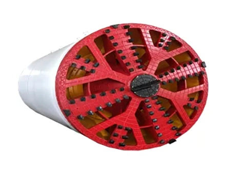
Կտրող գլխի կոնֆիգուրացիան և սարքավորումը խիտ ավազի համար
Միկրոթունելավորման մեքենայի կտրող գլուխը, որն օգտագործվում է խիտ ավազում, պետք է հատուկ կոնֆիգուրացված լինի մաշվող, բարձր շփման պայմաններում կտրելու համար: Սկավառակաձև կտրիչները, կարբիդային ծայրով քաշվող սրվածքները և ամուր սկրեպերների դասավորությունները ավելի նախընտրելի են, քան ստանդարտ մեղմ հողերի համար նախատեսված կտրիչ գործիքները, որոնք արագ մաշվում են խիտ գրանուլյար հողերում և ժամանակի ընթացքում նվազեցնում են կտրման արդյունավետությունը: Կտրման արդյունավետության նվազումը ստիպում է օպերատորին մեծացնել մխրճման ուժը՝ առաջընթացի արագությունը պահպանելու համար, ինչը լրացուցիչ մաշում է բոլոր մխրճման բաղադրիչները:
Կտրիչ գլխի ճակատի բացման հարաբերությունները ազդում են նյութի մուտքի աստիճանի վրա կտրման խցիկ՝ ավելի կամ պակաս ագրեսիվ ձևով: Խիտ ավազում բարձր բացման հարաբերությունը նպաստում է նյութի հոսքին, սակայն կարող է թույլ տալ հողի աղեղնավորվել բացվածքների միջև ճակատի վրա, ինչը մեծացնում է ճակատի դիմադրությունը: Բացման հարաբերության և ճակատի աջակցման պահանջների միջև հավասարակշռությունը մեքենայի կոնֆիգուրացման որոշում է, որը ուղղակիորեն ազդում է շարժման ընթացքում անհրաժեշտ մխոցային ուժի վրա: Այս պարամետրերի նշանակման ժամանակ կոնկրետ նախագծի համար անհրաժեշտ է խորհրդատվություն ստանալ խիտ ավազում փորձ ունեցող արտադրողներից և կառուցապատողներից:
Մշտադիտման համակարգերը, որոնք զգուշացնում են օպերատորներին մեքենայի սղոցավոր գլխի գործիքների մաշվածության մասին շարժման ընթացքում, արժեքավոր ներդրում են խիտ ավազային նախագծերում: Երբ սղոցավոր գործիքները կտրուկ մաշվում են, մեքենան նույն առաջխաղացման արագությունը պահպանելու համար ավելի մեծ ճնշում է պահանջում, իսկ աճած ձգող ուժը կարող է չլինել անմիջապես նկատելի, եթե օպերատորները չունեն լավ վիճակում գործիքների դեպքում մեկ մետրում սպասվող ուժի հղումային տվյալներ: Գործիքների ակտիվ ստուգումը՝ մեքենայի չափսերի թույլատրած դեպքում մուտքի պատուհանների միջոցով, կամ պլանավորված ստուգման շարժումների իրականացումը, կանխում է աննկատ գործիքների կորուստը՝ այն չթույլատրելով վերածվել մանր թունելավորման մեքենայի կամ տեղադրված խողովակաշարի կառուցվածքային վնասի:
Խիտ ավազում ձգող ուժի կառավարման շահավետ շահագործման լավագույն մեթոդներ
Շարժման արագություն, ընդհատումների կառավարում և ուժի կառավարում
Հաստատուն առաջընթացի արագությունը պահպանելը խիտ ավազում ջեկինգի ուժը վերահսկելու ամենաարդյունավետ եղանակներից մեկն է: Երբ միկրոթունելավորման մեքենան կանգնում է շարժման ընթացքում, շրջապատող խիտ ավազը սեղմվում է խողովակաշարի դեմ, և բենտոնիտային քսանյութի թաղանթը խախտվում է: Կանգից հետո վերսկսելը գրեթե միշտ պահանջում է ավելի բարձր սկզբնական ջեկինգի ուժ, քան հաստատուն շարժման պայմաններում, երբեմն՝ զգալիորեն ավելի բարձր: Շարժումների պլանավորումը՝ նախնական նյութերի մատակարարման, նախապես նախատեսված արտակարգ իրավիճակների լուծման ընթացակարգերի և խողովակների տեղադրման ընթացքում միջանցումներից խուսափող հերթափոխների կազմակերպման միջոցով՝ անմիջապես նվազեցնում է համակարգի կողմից կարողանալու համար անհրաժեշտ առավելագույն ջեկինգի ուժի պահանջը:
Երբ ընդհատումները խուսափելի են, կանգի ժամանակ օղակաձև գոտում բենտոնիտի ճնշման պահպանումը օգնում է պահպանել քսանյութային թաղանթը և նվազեցնել հողի սեղմումը խողովակի մակերեսի դեմ: Որոշ միկրոթունելային մեքենաների կառուցվածքներ ներառում են ինքնաշատացված քսանյութի պահպանման ցիկլեր, որոնք ակտիվանում են կանգի ժամանակ, և այս հատկանիշը հատկապես արժեքավոր է խիտ ավազում, որտեղ քսանյութի քայքայման արագությունը բարձր է: Ջեկինգի ուժի վերսկսումը վերահսկվող և աստիճանաբար կիրառվող եղանակով՝ այլ ոչ թե հանկարծակի լիարժեք մխոցման կիրառմամբ, նվազեցնում է խողովակաշարի և մեքենայի բաղադրիչների վրա ազդող հարվածային բեռը:
Անընդհատ գրանցումը ամբողջ շարժման ընթացքում շահագործման թիմին տրամադրում է իրական ժամանակում տեղեկատվություն մեքենայի բարձրացման ուժի փոփոխվող պրոֆիլի մասին: Բարձրացման ուժի գրաֆիկի կառուցումը շարժման հեռավորության վրա ցույց է տալիս միտումներ՝ շարժման երկարության աճին զուգընթաց ուժի աստիճանական աճ, հողի շերտերի փոփոխությանը կապված քայլային փոփոխություններ կամ տեղական դիմադրությունը ցույց տվող հանկարծակի վերելքներ: Լավ կազմակերպված նախագիծը օգտագործում է այս տվյալները՝ կանխատեսող որոշումներ կայացնելու համար շարժման ուժը կրիտիկական սահմաններին հասնելուց առաջ, այլ ոչ թե վնասների առաջացումից հետո, և դա ներառում է քսուքի կարգավորման, առաջընթացի արագության փոփոխության և միջանկյալ բարձրացման կայանների միացման հարցերը:
Քսուքի համակարգի նախագծման և վերահսկման պրոտոկոլներ
Բենտոնիտային քսանյութի համակարգը նախագծի թիմերի կողմից ջեկինգի ուժը խիտ ավազում կառավարելու համար ակտիվորեն կարողացող ամենակարևոր փոփոխականն է: Համակարգի նախագծում պետք է հաշվի առնել ավազի բարձր թափանցելիությունը, որը պահանջում է ավելի մեծ ներարկման ծավալներ և ճնշումներ, քան համապատասխան երկարությամբ կապված հողերի դեպքում: Ներարկման բերանները պետք է տեղադրվեն մոտ միմյանց՝ սովորաբար յուրաքանչյուր երկու կամ երեք խողովակի երկարության վրա խիտ ավազում, իսկ բենտոնիտի խառնուրդը պետք է պատրաստվի այնպես, որ հողի անցքերի ջրի հետ շփվելիս արագ գելանա, որպեսզի դիմանա աններկայացված շրջանից դուրս միգրացիային:
Խեցային շարժման համակարգի քարուքի արդյունավետության վերահսկումը պահանջում է միաժամանակ հետևել ներարկման ծավալին և օղակաձև ճնշմանը: Եթե ներարկման ծավալը բարձր է, սակայն օղակաձև ճնշումը մնում է ցածր, ապա բենտոնիտը թափանցում է հողի մեջ՝ չստեղծելով կայուն քարուքի շերտ, և շփման նվազեցման արդյունքը չի ձեռք բերվում: Բենտոնիտի ծակոտկենությունը կարգավորելը, պոլիմերային ավելացումներ ավելացնելը կամ ժամանակավորապես ներարկման ճնշումը նվազեցնելը կարող են օգնել ստեղծել կայուն օղակաձև թաղանթ: Միկրոթունելավորման մեքենայի շարժման խումբը, որը իրական ժամանակում ակտիվորեն կառավարում է քարուքի արդյունավետությունը, միշտ կստանա ավելի ցածր մխումնային ուժեր, քան այն խումբը, որը պարզապես շահագործում է համակարգը ֆիքսված նախնական սահմանված արագությամբ:
Ճանապարհային աշխատանքներից հետո կատարված քսման գրառումները պետք է վերլուծվեն նախագծի ավարտման շրջանակներում և ներառվեն ստացված փորձի բազայում: Յուրաքանչյուր մետր ճանապարհի համար օգտագործված քսման ծավալի համեմատությունը դանդաղեցման ուժի տվյալների հետ թույլ է տալիս որոշել իրական սարքավորումների շփման նվազեցման չափը և օգնում է ճշգրտել շփման գործակցի ենթադրությունները հաջորդ նախագծերի համար՝ նմանատիպ հողային պայմաններում: Այս համակարգային բարելավման մոտեցումը բնորոշ է տեխնիկապես հասուն միկրոթունելավորման կատարողներին, որոնք տարբեր գետնային պայմաններում ապահովում են հաստատուն և կանխատեսելի դանդաղեցման ուժի ցուցանիշներ:
Հաճախադեպ տրվող հարցեր
Ի՞նչ է միկրոթունելավորման մեքենայի սովորական ընդհանուր դանդաղեցման ուժի միջակայքը խիտ ավազում:
Մանրաթելային մեքենայի ընդհանուր բարձրացման ուժը խիտ ավազում շատ տարբերվում է՝ կախված խողովակի տրամագծից, շարժման երկարությունից, խորությունից, ստորերկրյա ջրերի պայմաններից և քսանյութի արդյունավետությունից: Ջրի մակարդակից ստորև խիտ ավազով 100–200 մետր երկարությամբ միջին տրամագծի խողովակների համար ընդհանուր բարձրացման ուժը սովորաբար կազմում է 100–400 տոննա, իսկ որոշ մեծ տրամագծի կամ երկար շարժման նախագծերում միջանկյալ բարձրացման կայանների ներդրումից առաջ այն կարող է գերազանցել 600 տոննան: Նախագծի համար սահմանված արժեքները միշտ հաշվարկեք իրական հողային հետազոտության տվյալների հիման վրա՝ չօգտագործելով ընդհանուր հղման միջակայքեր:
Ինչպե՞ս է ստորերկրյա ջուրը ազդում խիտ ավազում մանրաթելային բարձրացման ուժի վրա:
Ստորերկրյա ջուրը նշանակալիորեն մեծացնում է ջակինգի ուժը խիտ ավազում՝ ավելացնելով հիդրոստատիկ ճնշում ճակատային դիմադրության հաշվարկի մեջ և մեծացնելով խողովակի տողի վրա ազդող էֆեկտիվ նորմալ լարումը, ինչը ամրապնդում է մակերևույթային շփման ուժը: Բարձր ջրատար շերտի տակ հագեցած խիտ ավազում միկրոթունելավորման մեքենայի շարժումը կարող է պահանջել 30–60 % ավելի մեծ ջակինգի ուժ, քան նույն շարժումը չոր պայմաններում: Ցանկացած խիտ ավազի նախագծման համար անհրաժեշտ են ստորերկրյա ջրերի ճշգրիտ բնութագրումը գեոտեխնիկական հետազոտության ընթացքում և նախագծային հաշվարկներում վատագույն դեպքի ստորերկրյա ջրերի մակարդակների օգտագործումը:
Կարո՞ւմ է բենտոնիտային քսուքը լիովին վերացնել մակերևույթային շփման ուժը խիտ ավազում:
Բենտոնիտային քսուքը զգալիորեն նվազեցնում է մաշկի շփման ուժը խիտ ավազում, սակայն չի կարող այն ամբողջությամբ վերացնել դաշտային պայմաններում: Խիտ ավազի բարձր թափանցելիությունը բենտոնիտը տեղաշարժում է օղակաձև գոտուց դուրս, հատկապես շարժման ընդհատումների ժամանակ, որի արդյունքում շփման գործակիցը պրակտիկայում միշտ բարձր է, քան իդեալական լաբորատոր պայմաններում: Լավ նախագծված քսուքավորման համակարգերը՝ բավարար քանակությամբ ներարկմամբ, համապատասխան բենտոնիտի բաղադրությամբ և շարժման ընթացքում ակտիվ մոնիտորինգով, կարող են ստանալ շփման գործակիցներ 0,1–0,15 միջակայքում խիտ ավազում, սակայն պահպանողական նախագծման դեպքում միշտ պետք է ենթադրել 0,2 կամ ավելի բարձր արժեքներ՝ հաշվի առնելով իրական աշխարհի փոփոխականությունը:
Երբ պետք է օգտագործել միջանկյալ մխրճման կայաններ խիտ ավազում կատարվող մխրճման ժամանակ:
Միջանկյալ բարձրացման կայանները պետք է հաշվի առնվեն այն դեպքում, երբ լրիվ շահագործման երկարության վրա հաշվարկված ընդհանուր բարձրացման ուժը մոտենում է կամ խողովակի առավելագույն կառուցվածքային կարողությանը, կամ հիմնական բարձրացման շրջանակի անընդհատ թույլատրելի մխուրճման ուժին: Խիտ ավազում ակտիվ քսուքավորման դեպքում ստանդարտ բետոնե բարձրացման խողովակների համար այս սահմանային արժեքը սովորաբար հասնում է 120–180 մետր երկարության շահագործման դեպքում: Միջանկյալ բարձրացման կայանների օգտագործման որոշումը պետք է կայացվի նախագծման փուլում՝ բարձրացման ուժի հաշվարկների հիման վրա, այլ ոչ թե ռեակտիվ կերպով՝ շինարարության ընթացքում, երբ միջամտության տարբերակները զգալիորեն սահմանափակ են և ավելի թանկ են:
Բովանդակության ցուցակ
- Խիտ ավազում միկրոթունելավորման մեքենայի վրա ազդող ուժերի հասկանալը
- Խիտ ավազի պայմաններում ընդհանուր բարձրացման ուժի հաշվարկը
- Բարձրացման ուժի սահմանման առաջ հողի հետազոտության պահանջներ
- Սարքավորումների ընտրություն և կոնֆիգուրացիա խիտ ավազային բարձրացման պայմաններում
- Խիտ ավազում ձգող ուժի կառավարման շահավետ շահագործման լավագույն մեթոդներ
-
Հաճախադեպ տրվող հարցեր
- Ի՞նչ է միկրոթունելավորման մեքենայի սովորական ընդհանուր դանդաղեցման ուժի միջակայքը խիտ ավազում:
- Ինչպե՞ս է ստորերկրյա ջուրը ազդում խիտ ավազում մանրաթելային բարձրացման ուժի վրա:
- Կարո՞ւմ է բենտոնիտային քսուքը լիովին վերացնել մակերևույթային շփման ուժը խիտ ավազում:
- Երբ պետք է օգտագործել միջանկյալ մխրճման կայաններ խիտ ավազում կատարվող մխրճման ժամանակ: